
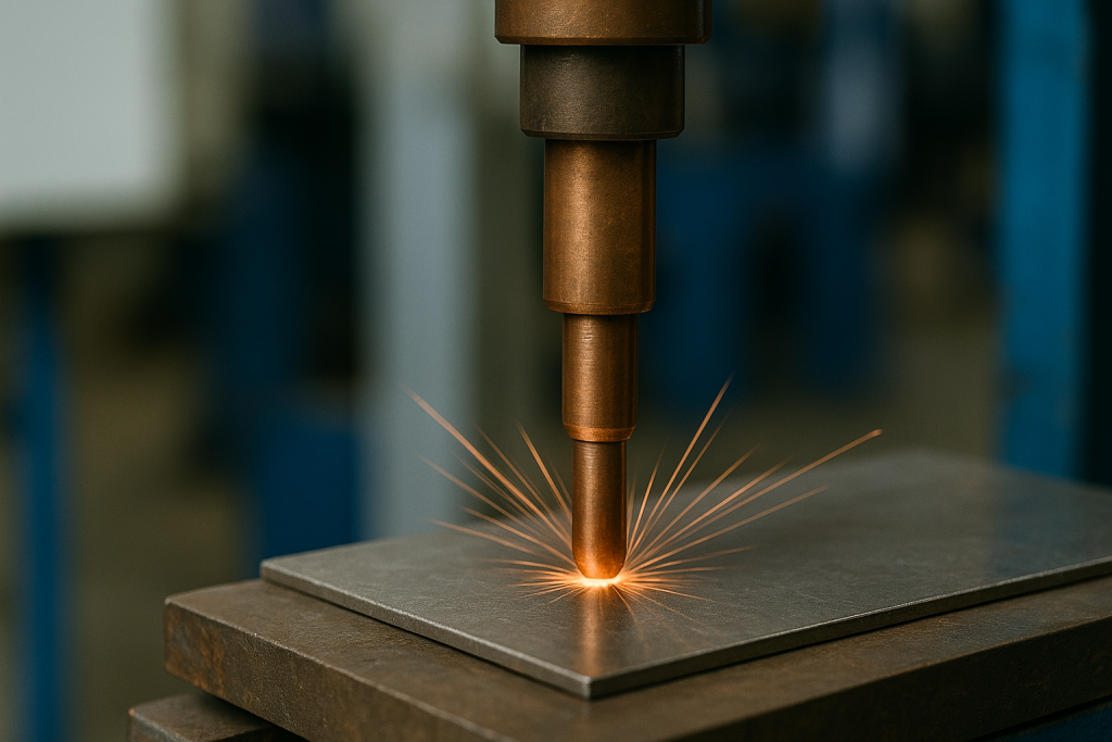
Resistance welding is a joining process that uses electric current and pressure to fuse metal parts together at their contact surfaces. Unlike arc welding methods that require filler metals or shielding gases, resistance welding relies on the heat generated when current passes through the metal’s natural electrical resistance. The process creates a localized molten pool—called a weld nugget—that solidifies under pressure to form a strong bond.
This method has become essential in modern manufacturing because of its speed, repeatability, and suitability for automation. From the body panels on your car to the sealed seams in household appliances, resistance welding quietly powers millions of joints every day. One common application of this technique is the resistance welding of structural steel, where strong, reliable joints are essential for maintaining the integrity and durability of large-scale constructions.
How Resistance Welding Works
The physics behind resistance welding is straightforward: when you force electrical current through metal, the material’s resistance converts electrical energy into heat. This phenomenon, known as Joule heating, concentrates thermal energy precisely at the joint interface. To fully understand the process, it helps to explore how resistance welding works and the key factors that influence weld quality and strength.
Here’s what happens during a typical resistance weld cycle:
Electrode positioning and squeeze time – Two copper-alloy electrodes clamp the workpieces together, applying force that brings the metal surfaces into intimate contact. This initial squeeze phase establishes proper contact resistance and current distribution before welding begins.
Current application and nugget formation – High amperage current (often thousands of amps) flows through the electrodes and workpieces for a precisely controlled duration—typically measured in cycles (1/60th of a second for AC systems) or milliseconds. Heat concentrates at the faying surfaces where contact resistance is highest. The metal at the interface reaches melting temperature and forms a molten nugget while the surrounding material acts as a heat sink.
Forging and solidification – After current stops, the electrodes maintain or increase clamping force during the hold time, forging the softened metal and allowing the nugget to solidify under pressure. This creates a consolidated weld with minimal porosity.
The amount of heat generated follows a simple relationship: Heat = I²RT, where I represents current, R is resistance, and T is time. Small changes in any of these parameters can dramatically affect weld quality, making precise control essential.
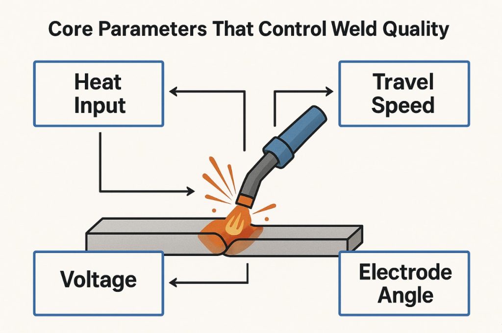
Core Parameters That Control Weld Quality
Three primary variables govern every resistance weld: current, time, and force. Among the key factors that influence weld strength and consistency, electrical parameters in resistance welding play a crucial role in determining heat generation and overall joint quality. Understanding how to balance these parameters determines whether you’ll produce strong, consistent joints or face quality issues.
Welding current determines how much heat you generate. Most resistance welding systems use AC power, though DC and mid-frequency direct current (MFDC) systems offer advantages for certain applications. MFDC units provide better control and efficiency, especially when welding aluminum or coated steels. Capacitive discharge systems deliver extremely rapid current pulses, ideal for delicate components in electronics. Too little current produces weak or incomplete nuggets; excessive current causes expulsion—when molten metal spatters from the joint—or electrode sticking.
Weld time must be long enough for the nugget to form and grow to adequate size, but not so long that excessive heating damages surrounding material or causes expulsion. Modern controllers measure time in milliseconds or AC cycles with precision. The squeeze time before current application and hold time after current stops are equally important for joint quality.
Electrode force affects both current density and contact resistance. Higher force increases the contact area and current flow path, requiring more current to achieve the same heating effect. Too little force results in surface burning and poor nugget formation; excessive force reduces contact resistance so much that insufficient heating occurs, and it can also collapse projections prematurely in projection welding applications. The electrodes must follow the material as it softens and expands during heating—a feature called electrode follow-up.
Material, Surface and Geometry Factors
Beyond the basic welding parameters, several material and physical factors influence the welding process and final joint quality.
Contact resistance varies with temperature, pressure, and surface condition. As temperature rises during the weld cycle, resistance decreases in most metals, which is why current or voltage may need adjustment mid-cycle. Surface contamination from oils, oxides, or dirt increases contact resistance unpredictably and can cause inconsistent heating or weak bonds.
Material properties fundamentally affect weldability. Metals with high electrical resistivity generate more heat for a given current, while materials with high thermal conductivity quickly conduct heat away from the weld zone. Dissimilar metal welding presents special challenges because different resistivities and melting points create asymmetric heating patterns. Aluminum-to-steel joints, for example, require specialized techniques to manage the aluminum’s high conductivity and steel’s higher melting point.
Surface coatings and geometry also matter. Galvanized steel’s zinc coating initially increases contact resistance but quickly vaporizes, requiring parameter adjustments compared to bare steel. In projection welding, the height, shape, and number of embossed projections determine current concentration and collapse dynamics. Electrode tip geometry—whether pointed, domed, or flat—affects current density distribution and nugget size in spot welding, while wheel electrode diameter and face width influence seam welding patterns.
Types of Resistance Welding
Resistance welding encompasses several distinct processes, each optimized for specific joint configurations and production requirements. Understanding the types of resistance welding methods is essential for selecting the right technique for your materials, ensuring strong and reliable welds every time.
Spot Welding (RSW)
Spot welding creates individual circular welds using pointed or domed electrode tips. It’s the most common resistance welding variant, responsible for joining sheet metal assemblies throughout the automotive industry. A typical car body contains thousands of spot welds connecting panels, doors, and structural components.
The weld nugget size correlates directly with the electrode tip contact area and the sheet thickness. Spot welding excels at joining overlapping sheets, usually between 0.5mm and 3mm thick per layer, though specialized equipment can handle thicker or thinner materials. The process is fast—often completing a weld in less than a second—and readily automated using robotic cells.
Seam Welding (RSEW)
Seam welding uses rotating wheel electrodes instead of stationary tips. As the wheels roll along the joint, they create a series of overlapping spot welds that produce a continuous, often leak-tight seam. The overlap between successive nuggets determines whether you achieve a gas-tight or liquid-tight joint.
This process is ideal for manufacturing containers, radiators, fuel tanks, and heat exchangers where hermetic sealing is required. Seam welding can operate in continuous mode, with current flowing constantly as the wheels rotate, or intermittent mode, where current pulses at intervals. The wheel diameter, face width, and rotation speed must be coordinated with welding parameters to maintain consistent quality.
Projection Welding (RPW)
Projection welding concentrates current at small, raised projections or dimples embossed into one of the workpieces. When the electrodes apply force, current flows through these high points, rapidly heating and collapsing them to form nuggets. This approach allows multiple welds to form simultaneously with a single set of large, flat electrodes.
Common applications include attaching nuts, brackets, and studs to sheet metal, as well as cross-wire welding for manufacturing wire mesh and reinforcement grids. The projection design is critical—projections must be tall enough to concentrate current but robust enough to maintain stability during the squeeze phase without premature collapse. Projection welding enables higher production rates than spot welding when joining multiple points on a part.
Butt and Upset Welding
Butt welding joins bars, plates, wires, or tubes end-to-end by clamping them in electrodes and applying current while the parts are in contact or very close proximity. The interfaces heat rapidly, and then force brings the softened ends together in a forging action called upsetting.
In upset welding, current continues flowing during the upset phase, while in flash welding (described next), current stops before upsetting. These processes often produce solid-state welds where grain structure continues across the joint with minimal melting. Butt welding is common in wire manufacturing, chain making, and joining structural members where uniform cross-sections are maintained.
Flash and Percussion Welding
Flash welding begins with the workpieces nearly touching. When current flows, small arcs or flashes occur at the contact points, rapidly heating the interface to molten or near-molten temperatures. The operator or machine then quickly forces the parts together, extruding molten metal and contaminants from the joint while forging a solid bond.
This process excels at joining large cross-sections—railroad rails, drill pipe, and structural tubes—where the high heating rate and upset action produce strong welds with full penetration. Flash welding can successfully join dissimilar metals that are difficult to weld by other resistance methods.
Percussion welding is a high-speed variant where capacitive discharge delivers an extremely rapid current pulse simultaneously with impact, creating a weld in milliseconds. It’s used for joining electrical terminals, thermocouple wires, and dissimilar metal combinations in electronics and aerospace applications.
Variants and Hybrids
Several specialized variations extend resistance welding capabilities. One-sided spot welding uses a single accessible surface with current returning through backing bars or special electrode configurations, useful when access is limited. Indirect spot welding and series spot welding create multiple simultaneous welds using different current path arrangements.
Micro resistance welding operates at reduced scale for electronics and medical devices, joining components smaller than 1mm with precisely controlled pulses. Weld bonding combines resistance spot welding with adhesive bonding to increase joint strength and seal against corrosion. Resistance brazing and resistance soldering use similar equipment but apply current to heat brazing alloys or solder rather than melting the base metal. Element welding uses wire electrodes for specialized applications, and self-piercing rivet welding integrates mechanical fastening with resistance heating.
Advantages and Limitations
Advantages
Resistance welding delivers several compelling benefits that explain its dominance in high-volume manufacturing. The process is exceptionally fast, typically completing welds in fractions of a second, which enables production rates exceeding thousands of welds per hour. This speed, combined with the process’s inherent repeatability, makes resistance welding ideal for automated assembly lines.
Low thermal distortion results from the concentrated heat input and short weld times. Unlike arc welding processes that heat larger zones and can warp thin materials, resistance welding minimizes dimensional changes. The absence of filler metals and shielding gases reduces operating costs and eliminates concerns about weld metal chemistry or atmospheric contamination. Material waste is minimal since no spatter, slag, or consumable electrodes are discarded.
The process integrates seamlessly with robotic systems and can be easily monitored with real-time quality control systems. Labor costs decrease because operators require less specialized training compared to manual arc welding crafts. Energy efficiency is relatively high since power flows only during the brief weld cycle.
Limitations
Resistance welding cannot solve every joining challenge. Practical thickness limitations constrain the process to sheet metals and relatively thin sections in most applications. While specialized equipment can weld materials up to 25mm or more, conventional systems work best below 6mm per layer. Very thick materials require prohibitively high current and force levels.
Highly conductive metals like copper and silver pose difficulties because they conduct heat away from the joint faster than sufficient melting can occur. These materials often require specialized alloys, higher currents, or alternative welding strategies. Aluminum presents challenges from both high conductivity and the tenacious oxide layer on its surface, though modern MFDC systems have improved aluminum welding success.
The process requires substantial electrical power infrastructure—systems typically draw from 10 kVA to several hundred kVA depending on application. Equipment costs are high, particularly for heavy-duty machines and robotic installations. Access to both sides of the joint is usually necessary, except in special one-sided configurations. Skilled setup and maintenance are required to optimize parameters, maintain electrodes, and troubleshoot quality issues.
Applications by Industry
Automotive manufacturing relies more heavily on resistance welding than perhaps any other industry. A single vehicle body might contain 3,000 to 5,000 spot welds joining panels, reinforcements, doors, hoods, and structural members. Robotic welding cells enable the high production rates and consistency demanded by automotive assembly. Projection welding attaches brackets, studs, and mounting points throughout the vehicle.
Appliance manufacturing uses seam welding extensively to create hermetic seals in refrigerator cabinets, water heater tanks, and HVAC components. Spot welding assembles washer and dryer frames, range bodies, and dishwasher tubs. The speed and low distortion of resistance welding align perfectly with appliance production volumes and quality requirements.
Aerospace applications favor resistance welding for aluminum airframe assembly, where low heat input preserves material properties and minimizes distortion in weight-critical structures. Spot and seam welding join wing skins, fuselage panels, and fuel tank components. Strict quality standards and traceability requirements drive extensive process monitoring in aerospace resistance welding.
Electronics and battery manufacturing use micro resistance welding and percussion welding for joining tabs, terminals, and conductors in batteries, circuit boards, and sensor assemblies. The precise control and minimal heat-affected zone protect sensitive components. Capacitive discharge systems deliver the rapid pulses needed for these delicate applications.
Construction and infrastructure projects employ flash welding to join reinforcing bar (rebar) in concrete structures and to create continuous railroad rail from shorter sections. The ability to weld large cross-sections and produce full-strength joints makes flash welding invaluable for these demanding applications.
Pipeline and tube manufacturing uses high-frequency resistance welding (a specialized variant) to continuously form and weld pipe from flat strip. Seam welding joins tube sections for heat exchangers, boilers, and structural applications.
Common Challenges and Quality Issues
Even with proper equipment, several factors can compromise resistance weld quality. Understanding these challenges helps operators prevent defects and maintain consistent output. For a deeper understanding of how metal sheets are joined efficiently, check out our guide on spot and seam resistance welding explained, which covers the key techniques, applications, and benefits.
Electrode wear and contamination gradually degrade weld quality over production runs. As electrode tips wear, their contact area increases, reducing current density and nugget size. Material pickup from the workpiece—particularly aluminum or coated steels—alters the electrode surface and electrical characteristics. Regular tip dressing, cleaning, or replacement is essential maintenance.
Material compatibility affects weldability in multiple ways. Aluminum and aluminum alloys oxidize rapidly, forming an insulating layer that disrupts current flow; surface preparation and specialized parameter schedules help overcome this. Stainless steel’s lower electrical conductivity compared to carbon steel requires different welding parameters. Galvanized and other coated steels introduce variables as coatings vaporize during welding.
Gaps and misalignment between workpieces prevent proper current flow and nugget formation. Resistance welding performs best with tight-fitting parts and controlled clamping. Excessive gaps require higher current, increasing expulsion risk and producing inconsistent welds.
Shunting occurs when current diverts through previous adjacent welds instead of concentrating at the intended location. This parallel current path reduces heating at the new weld site. Minimum spacing requirements between successive spot welds—typically three to four times the nugget diameter—help prevent shunting, though this can limit joint design flexibility.
Expulsion happens when internal weld pool pressure exceeds the electrode force restraint, ejecting molten metal from the joint. Expulsion weakens the weld by reducing nugget size and creates surface pitting. Careful parameter optimization maintains sufficient nugget growth without crossing into the expulsion zone. Real-time monitoring systems can detect and respond to expulsion events.
Residual stresses and distortion develop from rapid localized heating and cooling cycles, particularly in constrained assemblies. While generally lower than arc welding processes, thermal stresses can still affect dimensional accuracy in precision applications or contribute to cracking in brittle materials.
Multiple weld spacing becomes problematic as weld count increases in assemblies. Each new weld potentially creates a shunt path for subsequent welds, requiring careful sequencing and possible current adjustments.
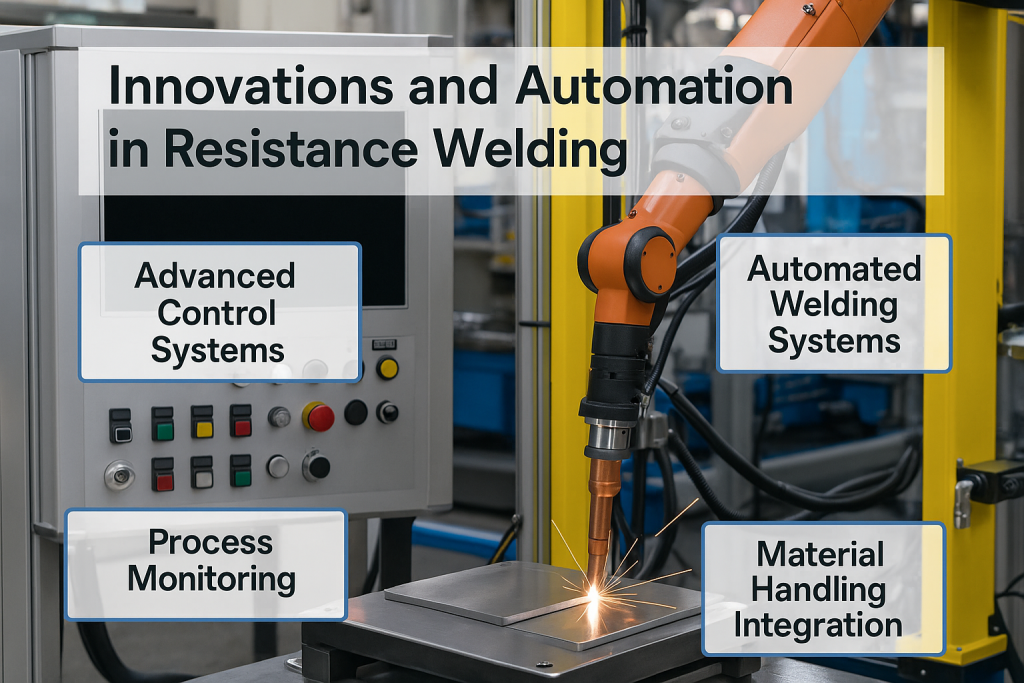
Innovations and Automation in Resistance Welding
Modern resistance welding increasingly integrates with digital technologies and intelligent systems to enhance quality, productivity, and flexibility.
Robotic welding cells dominate automotive and appliance production lines. Multi-axis robots position electrodes with repeatable accuracy, execute complex weld sequences, and adapt to part variations through programmed paths. Servo-actuated electrode systems provide precise force control throughout the weld cycle, responding dynamically to material behavior.
Artificial intelligence and real-time monitoring systems track weld signatures—voltage, current, resistance, and displacement curves—comparing each weld to learned patterns or target windows. Machine learning algorithms detect anomalies, predict electrode wear, and trigger alerts before quality degrades. Closed-loop control systems adjust parameters automatically to compensate for material thickness variations, part fit-up conditions, or electrode wear.
Industry 4.0 and IoT integration connects resistance welding equipment to plant-wide networks, collecting production data, monitoring machine health, and enabling predictive maintenance. Digital twins simulate welding processes virtually, optimizing parameters before production runs. Cloud-based analytics aggregate data from multiple machines and facilities, identifying trends and opportunities for improvement.
MFDC power supplies have largely replaced AC transformer systems in new installations. Operating at 1,000 Hz instead of 50-60 Hz, MFDC converters deliver more precise current control, reduce energy consumption, and improve power quality. Their lighter transformers enable more compact gun designs for robotic applications. Capacitive discharge systems store energy in capacitors and release it in extremely rapid pulses—microseconds to milliseconds—providing precise control for micro welding and difficult material combinations.
Automated production lines integrate resistance welding with material handling, part alignment, inspection, and post-weld processing. Vision systems verify part presence and alignment before welding. Automated tip dressers periodically recondition electrodes without operator intervention. Statistical process control charts track weld quality metrics, triggering maintenance or parameter adjustments when trends indicate degradation.
Resistance Welding vs Other Methods
Understanding how resistance welding compares to alternative joining processes helps you select the right approach for your application.
| Factor | Resistance Welding | MIG/TIG Welding | Laser Welding | Arc Welding (SMAW) |
| Speed | Very fast (0.1–2 sec/weld) | Moderate | Fast to very fast | Slow to moderate |
| Production cost | Low per part (high volume) | Moderate | High (equipment), low per part | Low equipment, higher labor |
| Precision/heat input | Concentrated, low distortion | Moderate heat zone | Extremely precise, minimal distortion | Large heat zone, higher distortion |
| Material thickness | Thin to medium (typically <6mm per layer) | Wide range, thick capable | Thin to medium, precision joining | Thick materials, structural |
| Consumables | No filler or gas; electrode maintenance | Filler wire, shielding gas | No filler (usually); shielding gas often | Electrodes, flux |
| Joint access | Both sides usually needed | One side access | One side access | One side access |
| Automation | Excellent, highly repeatable | Good | Excellent | Difficult, skilled labor |
| Initial investment | High (equipment, power) | Moderate | Very high | Low |
| Material versatility | Best for similar/compatible metals | Wide range, dissimilar capable | Wide range | Wide range |
Resistance welding excels when you need high-speed, repeatable joints in sheet metal assemblies and can invest in specialized equipment. MIG and TIG processes offer greater flexibility for varied joint configurations, thickness ranges, and field applications. Laser welding provides the ultimate precision and speed but at premium equipment costs. Traditional arc welding remains dominant for structural work, thick materials, and situations where portability and low initial investment matter more than production rate.
Frequently Asked Questions
Do I need filler metal or shielding gas for resistance welding?
No. Resistance welding joins materials by melting the base metal itself without adding filler. The brief weld time and electrode clamping pressure protect the molten nugget from atmospheric contamination, eliminating the need for shielding gas. This simplifies the process and reduces operating costs compared to arc welding methods.
What metals can be resistance welded?
Most common metals are suitable, including low-carbon steel, stainless steel, aluminum alloys, nickel alloys, copper (with difficulty), and titanium. Dissimilar metal combinations can be welded using specialized techniques like percussion welding or with intermediate layers, though matching electrical and thermal properties improves success rates. Highly conductive metals pose challenges, and very thick materials exceed practical limits for conventional equipment.
What limits thickness in resistance welding?
Several factors constrain thickness. Thicker materials require exponentially higher currents to generate sufficient heat at the interface, demanding larger power supplies and heavier electrodes. Increased thermal mass conducts heat away faster, reducing welding efficiency. Electrode force requirements increase substantially with thickness, requiring more robust equipment. Practical limits for conventional spot welding typically fall around 3-6mm per sheet, though specialized systems can handle greater thicknesses.
Why do expulsions happen and how can I prevent them?
Expulsion occurs when molten metal ejects from the joint due to internal pressure exceeding the electrode restraining force. Causes include excessive current, too-long weld time, insufficient electrode force, poor fit-up creating gaps, or material surface contamination. Prevent expulsion by optimizing the balance between current, time, and force; ensuring clean, tight-fitting parts; and monitoring for electrode wear. Real-time adaptive controls can detect the onset of expulsion and adjust parameters automatically.
Is resistance welding the same as spot welding?
Spot welding is one type of resistance welding, but the terms aren’t interchangeable. Resistance welding describes the entire family of processes that use electrical resistance heating and pressure to join metals—including spot, seam, projection, flash, and butt welding. Spot welding specifically refers to making individual circular welds between overlapping sheets using pointed electrodes. The distinction matters when specifying processes or discussing welding methods, though “resistance spot welding” clearly indicates the specific process.
Resistance welding continues to evolve as manufacturers demand faster production, higher quality, and greater flexibility. Digital controls, artificial intelligence, and automation are transforming what was once a purely mechanical process into a smart manufacturing technology. For applications requiring high-volume, repeatable joints in sheet metal assemblies, resistance welding remains an unmatched solution—powerful, efficient, and proven across industries from automotive to aerospace.